Tuesday, 1 November 2011

CIRC-07: Pushbuttons

Purpose: 
Turn on an LED by holding down a push button.


Equipment:
•1 x Arduino Uno
•1 x Breadboard
•7 x Wire
•2 x Pushbutton
•1 x LED
•1 x 560 Ohm Resistor
•2 x 10k Ohm Resistor

Reference:
http://www.oomlout.com/a/products/ardx/circ-07

Program Details: 
Pushbuttons are initialized the same way LEDs are.

Time to Complete: 
25 minutes

Results:
The first pushbutton lit up the LED when held down. However, the second pushbutton did not do anything.

Photos of Project: 


Tips:
Pushbuttons can be misplaced on the breadboard. If nothing is happening, try rotating your pushbuttons 90 degrees.

Further Work:
Code can be added to make the second pushbutton have a function.

Program Modifications:
The program is exactly the one from http://www.oomlout.com/a/products/ardx/circ-07

Program:
const int buttonPin = 2;     // sets the pin the button is connected to as a constant
const int ledPin =  13;      // sets the pin the LED is connected to as a constant
int buttonState = 0;         // int for reading state of button
void setup()
{
  pinMode(ledPin, OUTPUT); //initializes pin 13 as an output 
  pinMode(buttonPin, INPUT);   //initializes pin 2 as an input  
}
void loop()
 {
  //reads the state of the button and assigns it to buttonState
  buttonState = digitalRead(buttonPin);        

  if (buttonState == HIGH) {  //checks if the button is pushed then the LED will go on
     digitalWrite(ledPin, HIGH);
  }
  else {                     //if not the LED will go off
    // turn LED off:
    digitalWrite(ledPin, LOW);
  }
}

CIRC-06: Piezo Speaker

Purpose: 
Make the speaker play a simple tune using a range of frequencies.

Equipment:
•1 x Arduino Uno
•1 x Breadboard
•4 x Wire
•1 x Piezo Element

Reference:
http://www.oomlout.com/a/products/ardx/circ-06

Program Details: 
The same concepts are used, but for a different purpose for this lab. The initializing and loops are usually for the LED. This time, those simple concepts are used to play notes in a loop and initialize the speaker.

Time to Complete: 
10 minutes

Results:
The speaker in our Arduino set was not functioning properly. When we switched the speakers from another kit, the music began to play.

Photos of Project: 


Tips:
The speaker can be easily misplaced in the wrong holes. Double check to see if they are placed correctly.

Further Work:
We can attempt to use the creative part our minds and code a new song by using the different frequencies.

Program Modifications:
The program is exactly the one from http://www.oomlout.com/a/products/ardx/circ-06

Program:
int speakerPin = 9;
int length = 15; // the number of notes
char notes[] = “ccggaagffeeddc “; // creates an array of type char
int beats[] = { 1, 1, 1, 1, 1, 1, 2, 1, 1, 1, 1, 1, 1, 2, 4 }; /*creates an array of type int */
int tempo = 300;

void playTone(int tone, int duration) /* creates a function, playTone that has to parameters of type int */
 {
  for (long i = 0; i < duration * 1000L; i += tone * 2) {
    digitalWrite(speakerPin, HIGH);      //changes state of speakerPin to high
    delayMicroseconds(tone);             //delay equal to the value of tone
    digitalWrite(speakerPin, LOW); //changes state of speakerPin to low
    delayMicroseconds(tone);             //delay equal to the value of tone
  }
}
void playNote(char note, int duration) {
  char names[] = { 'c', 'd', 'e', 'f', 'g', 'a', 'b', 'C' };
  int tones[] = { 1915, 1700, 1519, 1432, 1275, 1136, 1014, 956 };

  // play the tone corresponding to the note name
  for (int i = 0; i < 8; i++) {
    if (names[i] == note) {
      playTone(tones[i], duration);      //send tones at i  and duration to playRone
    }
  }
}
void setup() {
  pinMode(speakerPin, OUTPUT);           //initializes pin 9 as an output
}
void loop() {
  for (int i = 0; i < length; i++) {
    if (notes[i] == ' ') {
      delay(beats[i] * tempo); // rest
    } else {
      playNote(notes[i], beats[i] * tempo);  //sends as parameters for playNote
    }


    delay(tempo / 2);
  }
}

CIRC-05: 74HC595 Shift Registers

Purpose: 
Get 8 LEDs to light up in a sequence using a shift register.


Equipment:
•1 x Arduino Uno
•1 x Breadboard
•20 x Wire
•8 x LED
•1 x Shift Register 74HC959
•8 x 560 Ohm Resistor

Reference:
http://www.oomlout.com/a/products/ardx/circ-05

Program Details: 
Shift register and shift bit values were introduced in the code.

Time to Complete: 
25 minutes

Results:
The circuit was built and the code was created, but it didn't work. After inspecting the circuit, we found that the 5V and ground wires were switched around by accident. Once the wires were changed, the LEDs lit up in  a sequence.

Photos of Project: 


Tips:
Again, watch out for the positive and negative parts of the LED. There's many parts to this lab, try to put the same piece of equipment consistently spaced out.

Further Work:
Make a different sequence rather than the one provided by the website.


Program Modifications:
The program is exactly the one from http://www.oomlout.com/a/products/ardx/circ-05

Program:

//used to set three control pins
int data = 2;
int clock = 3;
int latch = 4;

//Sets to variables as constants
int ledState = 0;
const int ON = HIGH;
const int OFF = LOW;
                        
//initializes the three control pins as outputs
void setup()
{
  pinMode(data, OUTPUT);
  pinMode(clock, OUTPUT);
  pinMode(latch, OUTPUT);
}

void loop()                     // continuously runs
{
  int delayTime = 100; //sets a delay time
  for(int i = 0; i < 256; i++){
   updateLEDs(i);
   delay(delayTime); //delay equal to the value of delayTime
  }
}

/*creates a void-type function, updateLEDs. Which Receives a parameter of type int from loop()*/
void updateLEDs(int value){
  digitalWrite(latch, LOW);     //changes the state of latch to low
  shiftOut(data, clock, MSBFIRST, value);
  digitalWrite(latch, HIGH);   // changes the state of latch to high
}

void updateLEDsLong(int value){
  digitalWrite(latch, LOW);    //changes the state of latch to low
  for(int i = 0; i < 8; i++){  //loop that will repeat 8 times
  int bit = value & B10000000;
                     
  value = value << 1;          
                     
  if(bit == 128){digitalWrite(data, HIGH);} /*if bit is set to 128 then the state of data will be changed to HIGH */
  else{digitalWrite(data, LOW);}            /*if bit isn't set to 128 then the state of data will be changed to LOW */
  digitalWrite(clock, HIGH);                //sets the state of clock to High
  delay(1);
  digitalWrite(clock, LOW);          //sets the state of clock to High
  }
  digitalWrite(latch, HIGH);  ////sets the state of latch to High }

//Creates an array, bits
int bits[] = {B00000001, B00000010, B00000100, B00001000, B00010000, B00100000, B01000000, B10000000};
//Creates an array, marks
int masks[] = {B11111110, B11111101, B11111011, B11110111, B11101111, B11011111, B10111111, B01111111};

//Creates a void-type function with to int type parameters
void changeLED(int led, int state){
   ledState = ledState & masks[led];  
   if(state == ON){ledState = ledState | bits[led];}
   updateLEDs(ledState);              //sends ledState to updateLEDs
}

CIRC-04: Servos

Purpose: 
Change LED on and off  the mini servo knob.

Equipment:
•1 x Arduino Uno
•1 x Breadboard
5 x Wire
•1 x Mini Servo
·    •1 x 3 Pin Header
·  
Reference:
http://www.oomlout.com/a/products/ardx/circ-04

Program Details: 
Servos are initialized the same way LEDs are. Objects and imports were used in the code.

Time to Complete: 
10 minutes

Results:
Done without a problem. The LED turned on when the servo was > 180 degrees and off when < 180 degrees.


Photos of Project: 


Tips:
Just like the LEDs, motors, and wires, the servos has a right way and a wrong way. If your LED isn't lighting up, try rotating the servos 180 degrees.

Further Work:
Create many different cases that will turn the LED on and off and different angles of rotation.


Program Modifications:
The program is exactly the one from http://www.oomlout.com/a/products/ardx/circ-04

Program:
#include <Servo.h> //imports directory Servo.h
Servo myservo;
                
int pos = 0; //Variable of the angle of rotation on the servo.

void setup()
{
  myservo.attach(9); //Attach to Pin 9
}

void loop()
{
  for(pos = 0; pos < 180; pos +=1)
  {                                  
    myservo.write(pos);
    delay(15);
  }

  for(pos = 180; pos>=1; pos-=1)
  {                               
    myservo.write(pos);
    delay(15);
  }
}

Monday, 31 October 2011

CIRC-03: Transistors & Motors

Purpose: 
Get the toy motor to spin.

Equipment:
•1 x Arduino Uno
•1 x Breadboard
•6 x Wire
•1 x Toy Motor
•1 x Transistor
•1 x Diode
•1 x 2.2k Ohm Resistor


Reference:
http://www.oomlout.com/a/products/ardx/circ-03


Program Details: 
Same methods as CIRC-01. Motors are initialized the same LEDs are.

Time to Complete: 
10 minutes

Results:
Forgot to upload the program, after uploading, the motor still wasn't spinning. Turns out the positive and negative on the motor was hooked up incorrectly. After fixing the connection, the motor began to spin.

Photos of Project: 

Tips:
Watch out for the pesky positive and negative connections.

Further Work:
We can change the speed or acceleration of the motor.


Program Modifications:
The program is exactly the one from http://www.oomlout.com/a/products/ardx/circ-03

Program:

int motorPin = 9;  // the pin the motor is connected to
                  
void setup()
 {
pinMode(motorPin, OUTPUT); //initalizes pin 9 as an output
 }

void loop()                     // Continuously runs
 {
  motorOnThenOff();             //Calls the function motorOnThenOff
 }


void motorOnThenOff() //creates a void-type function, motorOnThenOff
 {
  int onTime = 2500;  //time(in milliseconds) the motor is set to turn on for
  int offTime = 1000; // time(in milliseconds) the motor is set to turn off for

  digitalWrite(motorPin, HIGH); // changes the state of the pin9 to On
  delay(onTime);                // delay equal to the value of onTime
  digitalWrite(motorPin, LOW);  // changes the state of the pin9 to Off
  delay(offTime);               // delay equal to the value of offTime
 }
}

CIRC-02: Multiple LEDs

Purpose: 
Get 8 LEDs to blink on and off in a sequence.

Equipment:
-8 x LED
-10 x Wires
-8 x 560ohm resistor
-1 x Arduino Uno
-1 x Breadboard

Reference:
http://www.oomlout.com/a/products/ardx/circ-02

Program Details: 
This experiment had included arrays. functions, and for loops in the code. It was fairly simple to pick up since the Arduino language is similar to Java.

Time to Complete: 
20 minutes

Results:
No errors with this experiment, LEDs lit up without a problem.
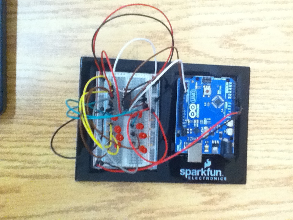
Photos of Project: 


Tips:
Similar to CIRC-01, just with 8 LEDs this time. Keep your LEDs, resistors, and wires consistently spaced out.

Further Work:
Change the sequence by playing with the order of the on and off lines of code.

Program Modifications:
The program is exactly the one from http://www.oomlout.com/a/products/ardx/circ-02

Program:

//An array that hold the pin each LED is connected to
int ledPins[] = {2,3,4,5,6,7,8,9};

void setup()
{
  for(int i = 0; i < 8; i++)      //loop to initialize each pin as an output
  {  
      pinMode(ledPins[i],OUTPUT); 
  }                                   
 
}


void loop()                     // Continuously runs
{
  oneAfterAnotherNoLoop();   //calls the function oneAfterAnotherNoLoop 
}
 

void oneAfterAnotherNoLoop()
 {
  int delayTime = 100; //sets a delay time
//turns LEDs on
  digitalWrite(ledPins[0], HIGH);  /*changes state of LED connected to pin 2  to high(on)*/
  delay(delayTime);                //delay equal to the value of delayTime
  digitalWrite(ledPins[1], HIGH);  /*changes state of LED connected to pin 3  to high(on)*/
  delay(delayTime);                //delay equal to the value of delayTime
  digitalWrite(ledPins[2], HIGH);  /*changes state of LED connected to pin 4  to high(on)*/
  delay(delayTime);                //delay equal to the value of delayTime
  digitalWrite(ledPins[3], HIGH);  /*changes state of LED connected to pin 5  to high(on)*/
  delay(delayTime);                //delay equal to the value of delayTime
  digitalWrite(ledPins[4], HIGH);  /*changes state of LED connected to pin 6  to high(on)*/
  delay(delayTime);                //delay equal to the value of delayTime
  digitalWrite(ledPins[5], HIGH);  /*changes state of LED connected to pin 7  to high(on)*/
  delay(delayTime);                //delay equal to the value of delayTime
  digitalWrite(ledPins[6], HIGH);  /*changes state of LED connected to pin 8  to high(on)*/
  delay(delayTime);                ////delay equal to the value of delayTime
  digitalWrite(ledPins[7], HIGH);  /*changes state of LED connected to pin 9  to high(on)*/

  delay(delayTime);                //delay equal to the value of delayTime
 //Turns LEDs off
  digitalWrite(ledPins[7], LOW);  //*changes state of LED connected to pin 2  to high(on)*/
  delay(delayTime);                //delay equal to the value of delayTime
  digitalWrite(ledPins[6], LOW);  //*changes state of LED connected to pin 3  to high(off)*/
  delay(delayTime);                //delay equal to the value of delayTime
  digitalWrite(ledPins[5], LOW);  //*changes state of LED connected to pin 4  to high(off)*/
  delay(delayTime);                //delay equal to the value of delayTime
  digitalWrite(ledPins[4], LOW);  //*changes state of LED connected to pin 5  to high(off)*/
  delay(delayTime);                //delay equal to the value of delayTime
  digitalWrite(ledPins[3], LOW);  //*changes state of LED connected to pin 6  to high(off)*/
  delay(delayTime);                //delay equal to the value of delayTime
  digitalWrite(ledPins[2], LOW);  //*changes state of LED connected to pin 7  to high(off)*/
  delay(delayTime);                //delay equal to the value of delayTime
  digitalWrite(ledPins[1], LOW);  //*changes state of LED connected to pin 8  to high(off)*/
  delay(delayTime);                //delay equal to the value of delayTime
  digitalWrite(ledPins[0], LOW);  //*changes state of LED connected to pin 9  to high(off)*/
  delay(delayTime);                //delay equal to the value of delayTime
 } 

}

CIRC-01: Blinking LED

Purpose: 
Get one LED to blink on and off.

Equipment:

-1 x Arduino Uno
-1 x Breadboard
-3 x Wire

-1 x LED
-1 x 560 Ohm Resistor

Reference:
http://www.oomlout.com/a/products/ardx/circ-01

Program Details: 
This experiment was a little introduction to Arduino. It shows the basic code structure and how it relates to what's happening on hardware.

Time to Complete: 
5 minutes

Results:
The LED lit up with no problems.
Photos of Project: 


Tips:
Straight forward experiment, just make sure that the LED is in the right way (long side is positive).

Further Work:
I can try to make it blink faster or slower by changing the delay.

Program Modifications:
The program is exactly the one from http://www.oomlout.com/a/products/ardx/circ-01

Program:

int ledPin =  13;    // the pin the LED is connected to.
 
// The setup() method runs once, when the sketch starts
 
void setup()  
{                
    pinMode(ledPin, OUTPUT); //initializes pin 13 as an output   
}
 
 
void loop()               //Continuously runs     
{
  digitalWrite(ledPin, HIGH);   // changes the state of ledPin to high(on)
  delay(1000);                  // delay equal to the 1000 millisecons
  digitalWrite(ledPin, LOW);    // changes the state of ledPin to low(off)
  delay(1000);                  // delay equal to the 1000 millisecons
}